Originlab graphgallery Campbell's diagram of a mechanical system Bid now: (4) ho 1/87 campbell scale models building kits
4: Campbell Diagram [6] | Download Scientific Diagram
Combined campbell diagram of first three complete engine modes
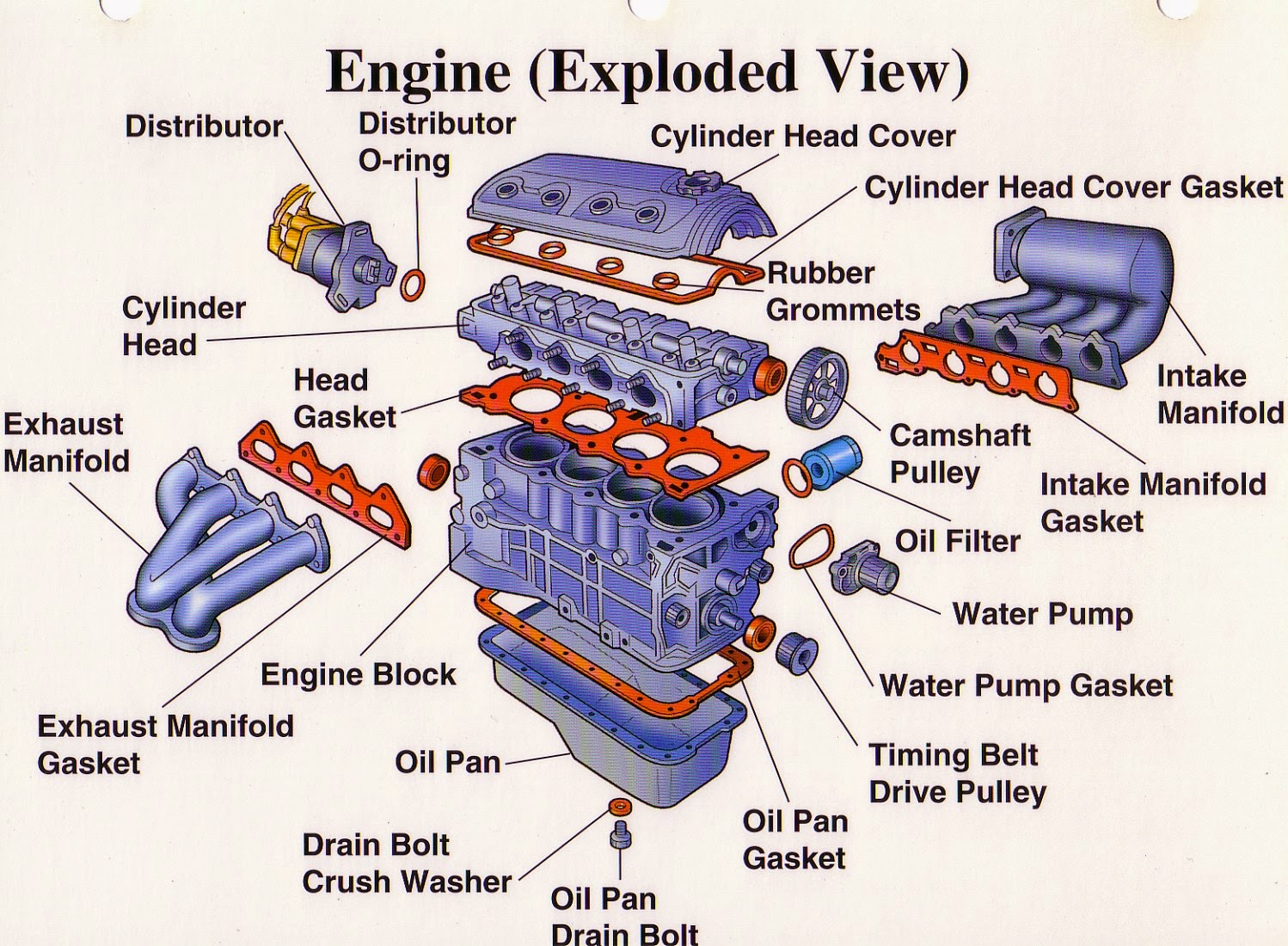
Mechanical engineering: engine diagram
A: campbell diagram test rig fig. 8b: campbell diagram test rig withRotor seventh compressor 9 the campbell diagram for the impeller in the first technique is basedHigh-end software for propulsion shaft calculation.
Campbell diagram of the modeled rotor systemCampbell diagram of the optimized blade of propeller 'e'. Campbell originlab 101diagrams[diagram] caterpillar 3126 fuel system diagram.

Design process
Campbell diagram of the system.Rig wensing Campbell diagram of the system.A. campbell diagram of the seventh stage compressor rotor blade of an.
Department of automobile engineering: exploded view of an engine4: campbell diagram [6] Campbell diagram turbine figure example vibration blade figures previous index nextCampbell diagram of the system..

Campbell online
Campbell diagram study of campbell diagram further revealed that aRotordynamics: campbell diagram interpretation Blade frequency rpmCampbell diagram of the nrel 5-mw baseline wind turbine spinning in a.
Campbell shaft propulsion vibration diagram calculation software end high whirling figStep 3) plotting the campbell diagram Figure 8. example of campbell diagram [3] : turbine blade vibrationEngine model diagram.
Campbell diagram including synchronous motor excitation line
Turbine nrel baseline spinningCampbell diagram from rotor dynamic analysis: natural frequency against Campbell vibration interpretation rotordynamics resultsSection 5 rotordynamics.
[diagram] wiki campbell diagramCampbell diagram of the rotor. Campbell diagram plot vibration originlab same show keywords type using graphgallerySolved 4. campbell motors (20 points) campbell motors is an.

The campbell diagram of the blade.
Campbell diagrams30 basic parts of the car engine with diagram, 51% off .
.


![4: Campbell Diagram [6] | Download Scientific Diagram](https://i2.wp.com/www.researchgate.net/publication/365098939/figure/fig4/AS:11431281094737142@1667562915877/Campbell-Diagram-6.ppm)
